|
My Imme
Refurbishment of my Imme (note: lots of pictures, download can take a while)
2016 meeting of the Imme Freundeskreis in Immenstadt
Imme company pictures
Imme company drawings
Technical (company) drawings Imme
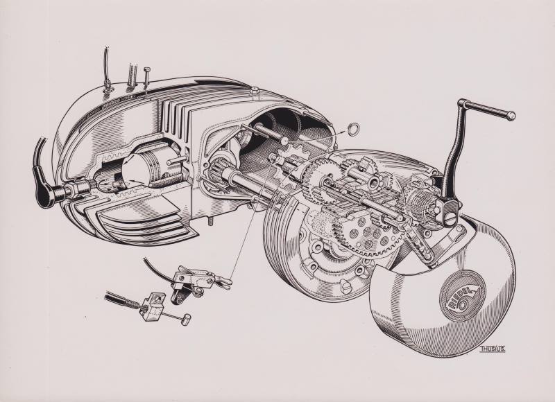
I have some photographic reproductions of old technical drawings made by Thusius, that show construction details of the Imme R100. These drawings have been distributed by the Riedel company to motorcycle magazines to illustrate their articles about the Imme. On the backside they cary a stamp that indicates that they are original factory drawings, released for publication (see also the company pictures). The drawings can be found in many magazines from the Imme era.
The first two show the Imme engine:
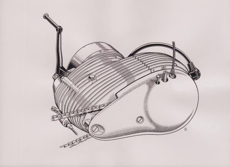
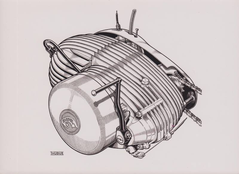
The ignition cover bears the Riedel logo. This is introduced together with the double sided bearing of the crankshaft in engine number 2963.
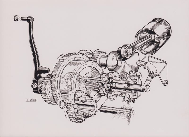
The next drawing is a combination of a "ghost view" and "exploded view", showing some of the engine's internal parts:
The next drawing shows the right engine cover with built-in air filter and the Bing carburettor:
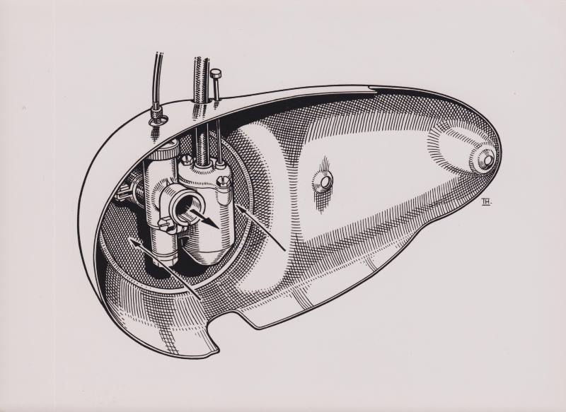
This drawing shows that originally the throttle cable and the fuel tube are led through round holes in the engine cover. On a lot of covers these holes have been modified into slots, to make demounting of the engine cover simpler.
The next 2 drawings show all internal parts of the engine:
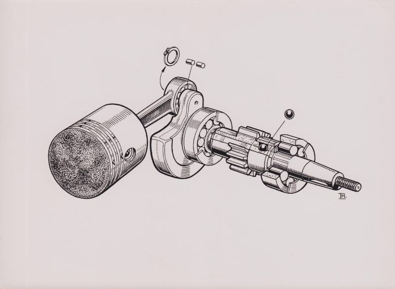
This is still the original version with the crank shaft with single sided bearing. The bearings are all loose roll bearings, and the connection rod is secured on the big-end with a circlip. The ball next to the gear is used to engage the gear to the axis.
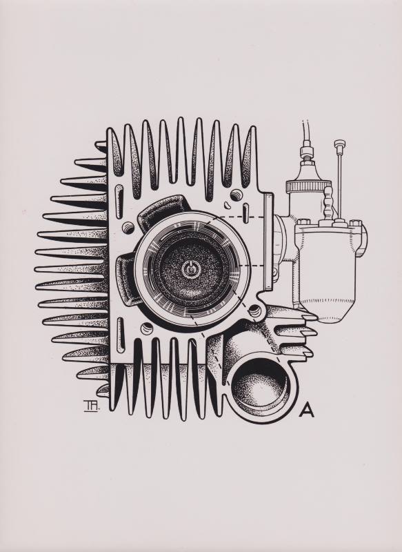
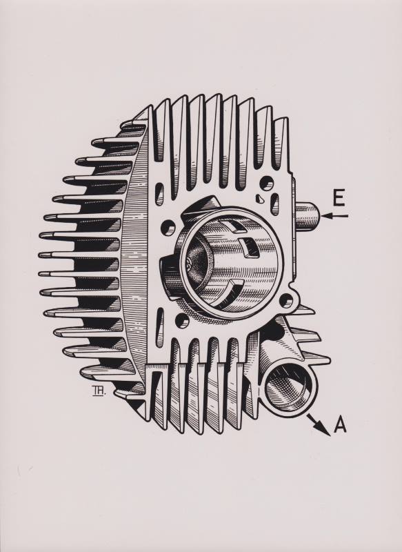
The following drawings give a look into the "blind" cilinder (in German: "sack-zylinder", a cilinder with the head fixed to the cilinder body, thus no loose head). The wide squish edge in the dome-shaped combustion chamber is visible, this was certain not a standard construction for a 2-stroke engine in those days.
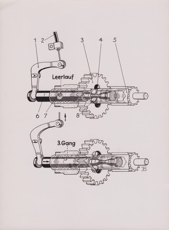
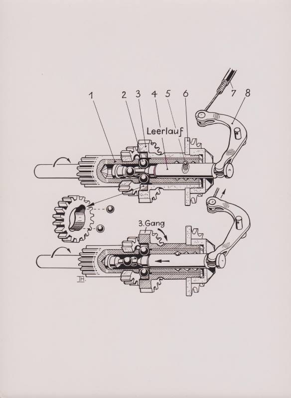
The next drawings elucidate how the gear shift mechanism works. The gear box operates with the "draw key" (in German: "Ziehkeil") principle: inside the hollow axis is a rod (key) that can be drawn to 3 different positions, and in each position pushes out a pair of steel balls to engage one of the gears to the axis. At the same time the 2 other gears are disengaged and can freely rotate around the axis.
This simple principle has later been used in numerous other motorised 2-wheelers, like the famous Zündapp mopeds. Later Norbert Riedel used the same principle with electric movement of the key in the Victoria Swing motorcycle and Peggy scooter.
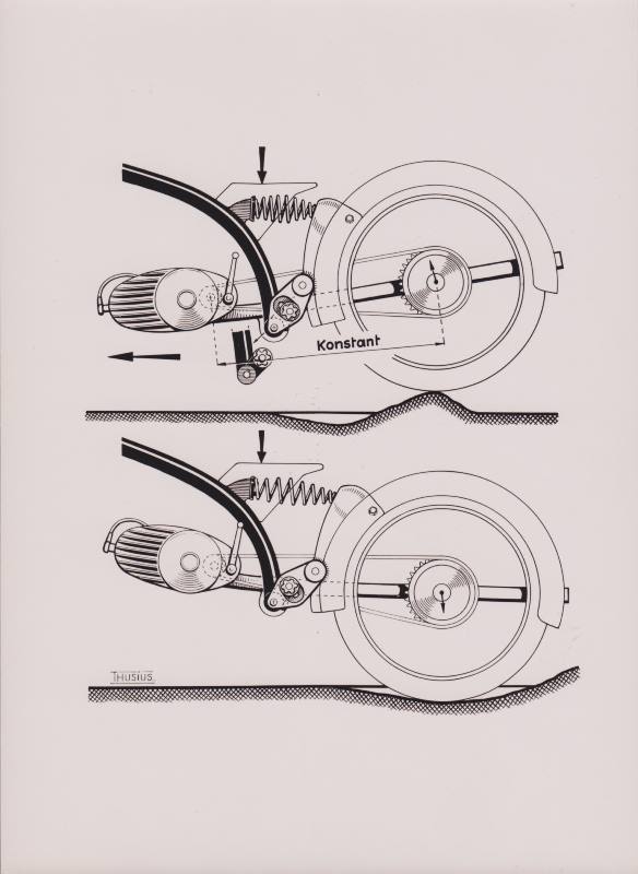
The next drawing shows how the rear suspension works. It demonstrates how the engine moves together with the swingarm, in this way keeping the chain tension constant:
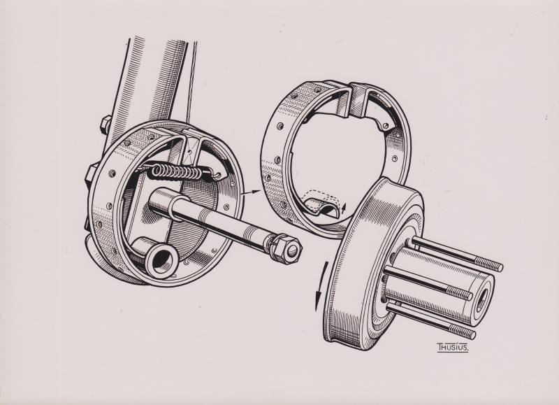
The operation of the brakes is illustrated in the next drawing. The brake does not contain 2 separate brake shoes as usual, but one almost circular expanding band. Because the mounting of the band opposite to the expander is flexible, the band can freely find its way to touch the brake drum over the maximum possible surface area. Also this principle was re-used in the Victoria Swing.
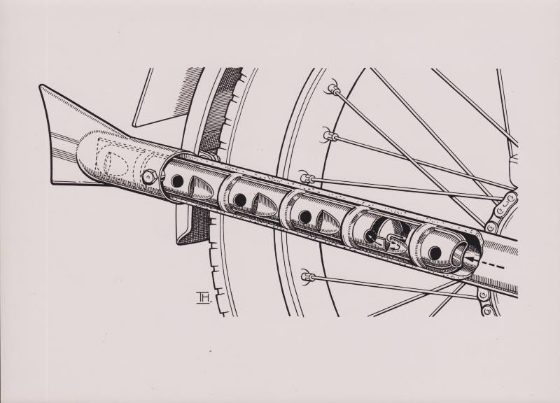
The last drawing shows the exhaust silencer:
Probably there must be much more of this kind of drawings. Comparable drawings are for instance used in the article in "Motor und Gasturbine".
|

